You might have thinking can a synchronous motor work as a synchronous generator?
Yes. Simply the thee phase supply is removed and only the DC field supply is retained. When the motor is run from external prime mover, they become an alternator or synchronous generator.
In a synchronous motor, AC power is supplied to the stator to generate a rotation magnetic field. DC power is supplied to the rotor which results in discrete North (N) and South (S) poles.
I guess you're talking about synchronous motor which require 3 phase supply to the stator winding and dc for field excitation.
Synchronous machines can be used as generators or motors. They are of 3-phase construction, even though some special exceptions can be found. A bulk of the applications are within power ranges roughly varying from a megawat level to several tenths (or even hundreds) of megawatts with rated ages from 3 KV to 15 kV.
A synchronous electric motor is an AC motor in which at steady state, the rotation of the shaft is synchronized with the frequency of the supply current, the rotation period is exactly equal to an integral number of AC cycles. Synchronous motors contain multiphase AC electromagnets on the stator of the motor that take a magnetic field which rotates in time with the oscillation of the line current. The rotor with permanent magnets or electromagnets turns in step with the stator field at the same rate and as a result, provides the second synchronized starting magnet field of any AC motor Asynchronous motor is termed doubly fed if it is supplied with independently excited multiphase AC electromagnets on both the rotor and stator.
The synchronous motor and induction motor are the most widely used types of AC motor. The difference between the two types is that the synchronous motor rotates at a rate locked to the line frequency since it does not rely on current induction to produce the rotor's magnetic field. By contrast the induction motor requires the rotor must rotate slightly slower than the AC alterations in order to inducement in the rotor winding Small synchronous motors are used in timing applications such as in synchronous cocks timers in appliances, tape recorders and precision servomechanisms in which the motor must operate at a precise speed speed accuracy is that of the power line frequency, which is carefully controlled in large Interconnected grid systems.
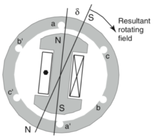
For motor operation, a balanced three-phase set of voltages is applied to the armature windings resting in the creation of a rotating magnetic field in the air gap between the stator and rotor. The stator and rotor fields combine to create a resultant field
The field winding is fed from a DC source either through springs or from a rotating rectifier, Thus, the rotor form an electromagnet with north and south poles, as shown. Of course, whenever we have opposite magnetic poles, we know there will be a force between them. That is the principle of operation of the synchronous motor.
The rotating field essentially puts the rotor field around with it. As the mechanical load is added to the shaft of the motor, the rotor field tends to fall behind the resultant field by an angle θ which is referred to as the power angle.
Also, as more load is added to the machine, the armature current increases to provide the extra power required Note that the speed of the rotating field is fed by the AC frequency, therefore, the synchronous motor operates only at one speed whether operating at no load of load.
FIGURE 1 Synchronous machine operating an a motor
One feature of the synchronous machine is that it has electrical sources one for the motor and one for the stator. Intuitively, it makes sense that as more power is required by the mechanical load on the motor, one or both of the magnetic field must get stronger. Essentially, ether winding can provide exciting current for the machine, which means the power factor of the motor can be varied by controlling the field current.
Generator Operation
Figure 2 shows around rotor synchronous machine. In case, as before, a DC voltage is applied to the field winding on the rotor, resulting in DC current and magnetic flux. The magnetic flux is symbolized by the arrows leaving the North Pole and returning to the South Pole. Of course the magnetic flux forms a closed path through the iron of the stator structure.
FIGURE 2 Synchronous machine operating as a generator
To operate the machine as a generator, the rotor is driven by a prime mover. As the rotative field sweeps by the armature conductors, voltages are induced in the armature windings.


I got some valuable points through this blog. Thank you sharing this blog.
ReplyDeleteStarlink Shop
You composed this post very carefully.Upgrading Residential Electrical Panels how much data is dazzling and furthermore a productive article for us. Continue to share this sort of articles, Much obliged.
ReplyDelete